Grinding wheel shapes according to DIN ISO 525, profiles and special shapes
Below you will find the standardized ISO shapes for grinding wheels and grinding segments according to DIN ISO 525.
We manufacture grinding wheels in all possible shapes and dimensions. We are also happy to respond to your individual challenges and develop custom-made grinding tools for you.
Wheel shapes
The effective surface of the grinding wheels is marked with an arrow.
| Drawing | Type | Designation | Dimensions | Example |
|---|---|---|---|---|
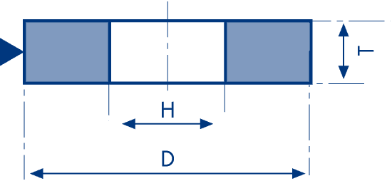 | 1 | Straight wheel | D x T x H | 300 x 20 x 127 |
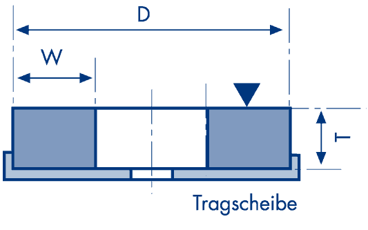 | 2 | Cylinder wheel glued to bearing disc | D x T – W | 457 x 125 – W 40 |
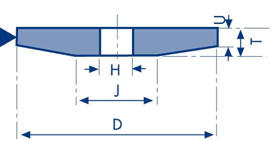 | 3 | Tapered wheel | D/J … x T/U … x H | 300/J100 x 32/U4 x 76,2 |
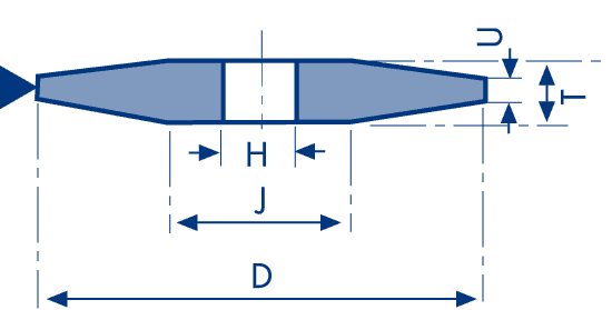 | 4 | Tapered wheel two sides | D/J x T/U x H | 150/J100 x 25/U3 x 20 |
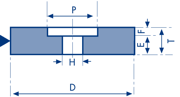 | 5 | Wheel, recessed one side | D x T x H – P … x F … | 508 x 50 x 304,8 – P390 x F20 |
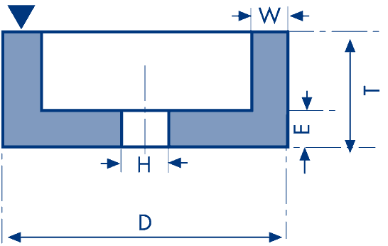 | 6 | Straight cup wheel | D x T x H – W … x E … | 200 x 63 x 76,2 – W20 x E20 |
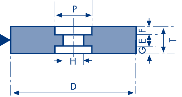 | 7 | Wheel, recessed two sides | D x T x H – P … x F/G … | 760 x 100 x 304,8 – P410 x F30/G30 |
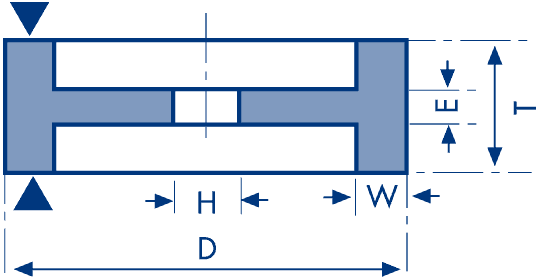 | 9 | Double cup wheel | D x T x H – W … x E … | 200 x 63 x 76,2 – W20 x E20 |
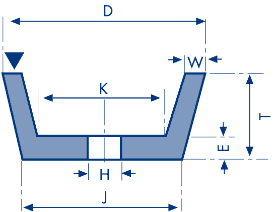 | 11 | Taper cup wheel | D/J … x T x H – W … x E … x K … | 150/J114 x 50 x 32 – W10 x E13 x K96 |
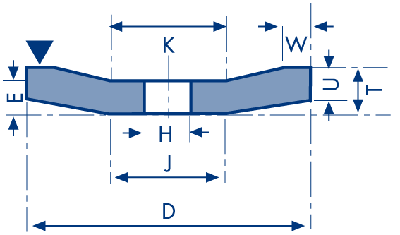 | 12 | Dish wheel | D/J … x T/U … x H – W … x E … x K … | 200/J92 x 32/U3,2 x 32 – W10 x E12 x K92 |
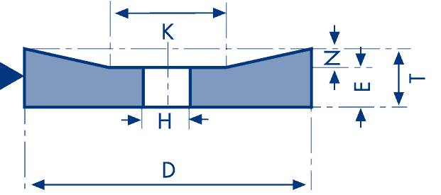 | 20 | Wheel, relieved one side | D/K … x T/N … x H | 508/K400 x 50/N20 x 304,8 |
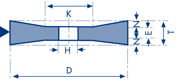 | 21 | Wheel, relieved two sides | D/K … x T/N … x H | 508/K400 x 50/N5 x 304,8 |
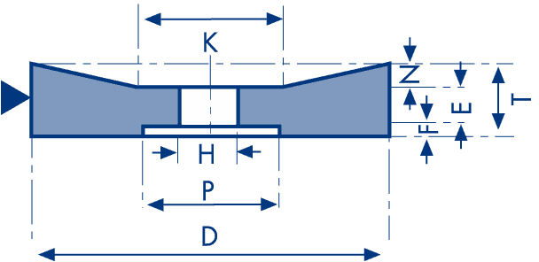 | 22 | Wheel, relieved one side, recessed other side | D/K … x T/N … x H – P … x F … | 508/K400 x 50/N5 x 304,8 – P390 x F10 |
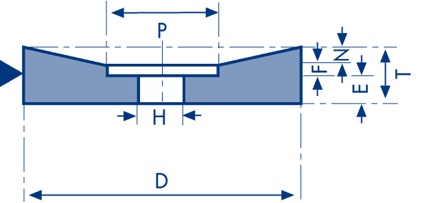 | 23 | Wheel, relieved and recessed same side | D x T/N … x H – P … x F … | 508 x 50/N5 x 304,8 – P390 x F10 |
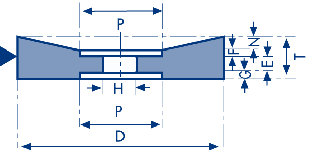 | 24 | Wheel, relieved and recessed one side, recessed other side | D x T/N … x H – P … x F … /G … | 508 x 80/N5 x 304,8 – P390 x F20 |
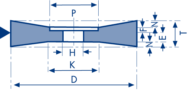 | 25 | Wheel, relieved and recessed one side, relieved other side | D/K … T/N … x H – P … x F … | 508/K400 x 80/N5 x 304,8 – P390 x F20 |
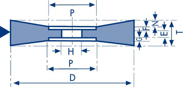 | 26 | Wheel, relieved and recessed both sides | D x T/N … x H – P … x F … /G … | 508 x 80/N5 x 304,8 – P390 x F10/G5 |
 | 3101 | Segment | B x C x L | 90 x 35 x 180 |
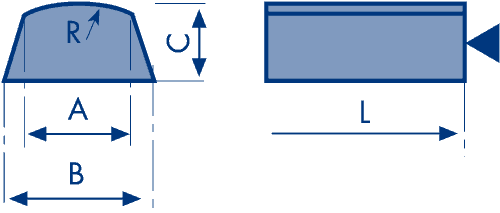 | 3102 | Segment | B/A x C x L R = … | 70/64 x 25 x 150 R=75 |
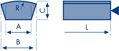 | 3103 | Segment | B/A x C x L R = … | 75/55 x 20 x 140 R=175 |
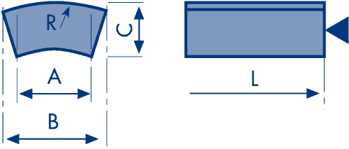 | 3104 | Segment | B/A x C x L R = … | 75/55 x 20 x 140 R=175 |
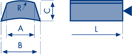 | 3105 | Segment | B/A x C x L R = … | 75/63 x 20 x 140 R=175 |
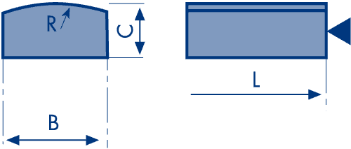 | 3108 | Segment | B x C x L R = … | 80 x 25 x 160 R=210 |
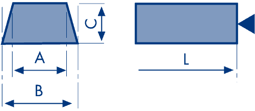 | 3109 | Segment | B/A x C x L | 70/64 x 25 x 110 |
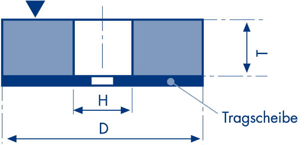 | 35 | Disc wheel, cemented on support | D x T x H | 450 x 63 x 200 |
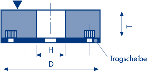 | 36 | Disc wheel with inserted nuts | D x T x H | 600 x 70 x 20 |
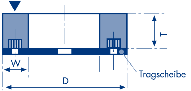 | 37 | Cylinder wheel with inserted nuts | D x T x W … | 350 x 70 x W40 |
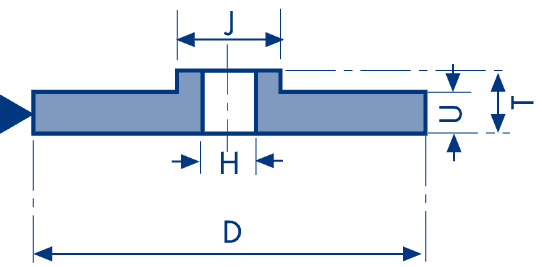 | 38 | Hubbed wheel | D/J x T/U x H | 610/390 x 32/20 x 304,8 |
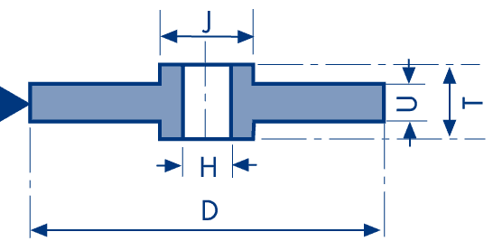 | 39 | Duplex hubbed wheel | D/J x T/U x H | 610/390 x 32/20 x 304,8 |
Wheel faces (peripheral shapes / profiles)
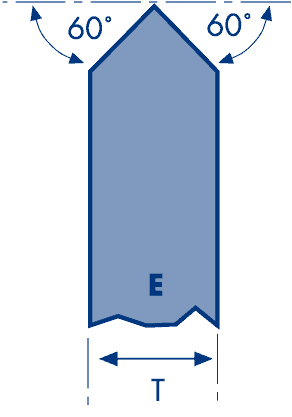
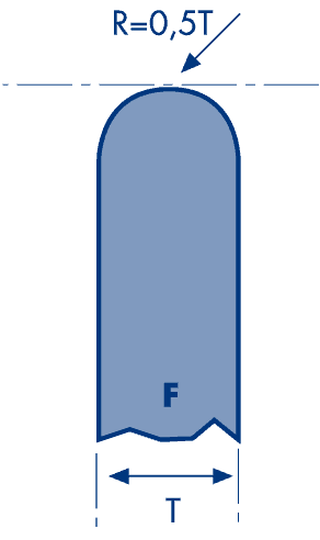
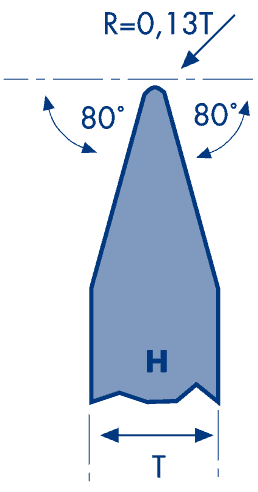
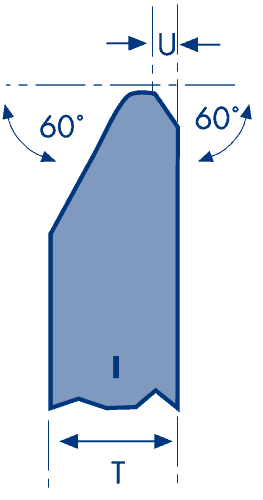
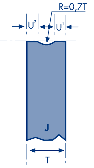
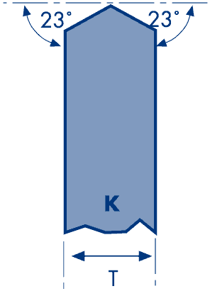
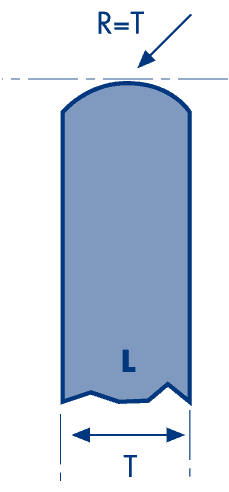
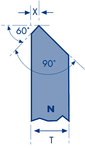
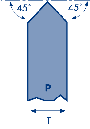
The peripheral shape describes the profile of a straight grinding wheel at the circumference (wheel faces).
U1 = 0,25 T (3 mm max.)
U2 = 0,33 T
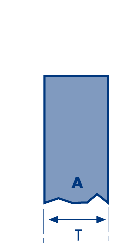 | 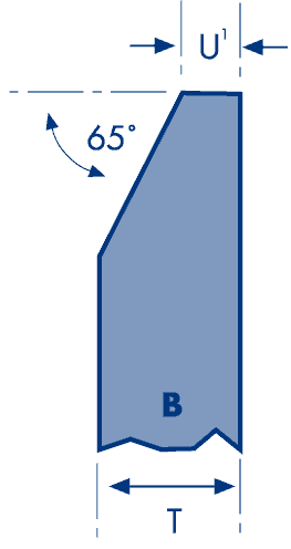 | 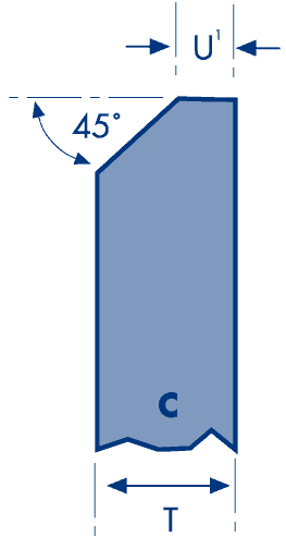 | 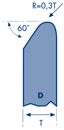 |  |
 |  |  |  |  |
 |  |  |  |
Special shapes
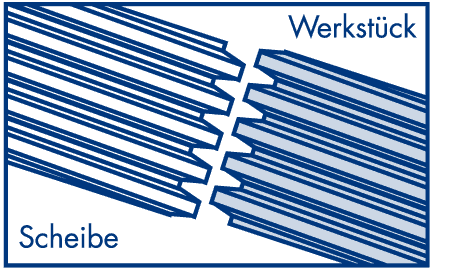
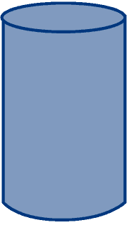
In addition to the special shapes shown here, we also manufacture the shape you require according to your drawing – just ask us!
| Multi-layer wheels | Impregnated (soaked) wheels | Worm wheels (Reishauer profile) | Partly soaked wheels | Grinding cylinders |
 |  |  |  |  |
